

A fiber optic patch panel—sometimes called a fiber distribution panel—is a rack‑mounted unit designed to neatly terminate, organize, and manage fiber‑optic cables. Serving as the network’s centralized junction, it provides secure ports for both incoming and outgoing fibers, streamlining connection changes and upkeep. By housing all terminations in one accessible enclosure, it makes routine maintenance, troubleshooting, and network reconfiguration faster and more reliable.
What Is a Fiber Optic Patch Panel?
A fiber optic patch panel is a centralized enclosure engineered to organize, manage, and interconnect fiber‑optic cables within data centers, telecommunications rooms, and other high‑density network environments. Its core functions are the termination, interconnection, and distribution of optical fibers, greatly simplifying network deployment, maintenance, and future upgrades.
Core Functions of a Fiber Optic Patch Panel
Connection
Provides front‑facing ports where fiber patch cords from different devices or routes can be mated, enabling seamless signal transmission.
Uses adapters (e.g., SC, LC) to secure connector end‑faces in the panel and ensure precise optical alignment.
Internal splice trays store excess fiber slack and protect fusion‑spliced joints, maintaining consistent signal quality and reliability.
Management
Offers a structured layout and clear labeling to centralize and organize fiber runs, making it easy to identify, trace, and maintain individual lines.
Includes built‑in routing guides, tie‑points, and slack storage areas to prevent cable tangles and accidental damage.
Supports testing and reconfiguration: network technicians can quickly isolate faults, reroute traffic, or add new links without disturbing the core cabling.
Protection
Splice trays and protective sleeves shield delicate fibers and fusion points from dust, moisture, and mechanical impacts.
Engineered to enforce a minimum bend radius, preventing micro‑bends that could degrade optical performance.
Expansion
Many patch panels integrate additional modules—such as splitters, WDM mux/demux units, or optical switches—so that more complex network functions can be housed within the same footprint.
Key Components of a Fiber Optic Patch Panel
Enclosure/Chassis
Rugged steel housing (19″, 21″, or 23″ rack‑mount, or wall‑mount) often in high‑density form factors that can cut rack usage by up to 75%.
Adapter Faceplates
Interchangeable panels that hold couplers. Typical densities include 6, 12, 24, or 48 ports per faceplate; high‑density versions can accommodate up to 96 fibers in just 1U of rack space.
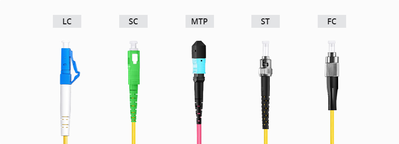
Connectors & Adapters
Interface incoming and outgoing fibers. Standard connector families include LC, SC, FC, ST, and MPO/MTP, color‑coded (e.g., blue for OS2 single‑mode, aqua for OM3/OM4 multimode) to match fiber specifications.
Splice Tray
A protected shelf for organizing and storing fusion‑spliced fiber pigtails, maintaining bend radius and preventing micro‑bends.
Cable Management Accessories
Fiber guides, Velcro straps, and slack organizers keep cables neat, reduce stress on connections, and promote proper airflow.
Labeling System
Numbered ports with writable strips or flip‑cards to simplify identification, documentation, and troubleshooting.
Strain Relief & Protection
Internal grommets, bushings, and clamp mechanisms that prevent excessive pulling force and sharp bends at entry points.
Types of Fiber Optic Patch Panels
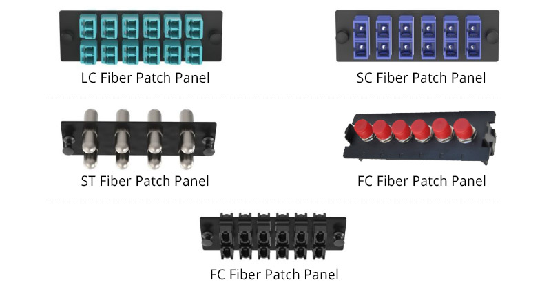
By Connector Style
LC/SC/FC/ST panels: Tailored to the physical dimensions and coupling methods of each connector.
MPO/MTP panels: Designed for parallel optics, combining 12–24 fibers into a single rectangular ferrule.
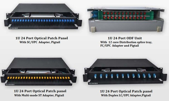
By Rack Unit (U) Height
1U–4U options: Support from 12 up to 288+ fibers, balancing density with accessibility.
By Mounting Format
Rack‑mount: Standard 19″ or 23″ rail installation.
Wall‑mount: Compact enclosures for remote or edge‑site deployments.
Drawer/Rotary types: Offer pivoting or sliding access for ultra‑high‑density installations.
By Fiber Mode
Single‑mode (e.g., ITU‑G.657) vs. Multimode (OM3/OM4), with color‑coding for rapid visual identification.
By Port Count
Options range from compact 6‑port panels to expansive 48‑port units and high‑density arrays with 144–216 ports per 1U.
Choosing the right combination ensures optimal port density, ease of access, and room for future growth.
Importance of Fiber Optic Patch Panels in Networks
Centralized Management
Organizes hundreds or thousands of fiber connections in a single location, greatly simplifying troubleshooting and documentation.
Scalability
Modular faceplates and unloaded (blank) panels allow incremental port additions or adapter upgrades without disturbing existing assemblies.
Reliability
Proper termination, bend‑radius protection, and strain relief minimize connector failures and signal degradation.
Operational Efficiency
Enables faster provisioning and maintenance, reducing labor costs and network downtime.
Space Optimization
High‑density panels free precious rack space for additional servers, switches, or storage.

0 Comments